|
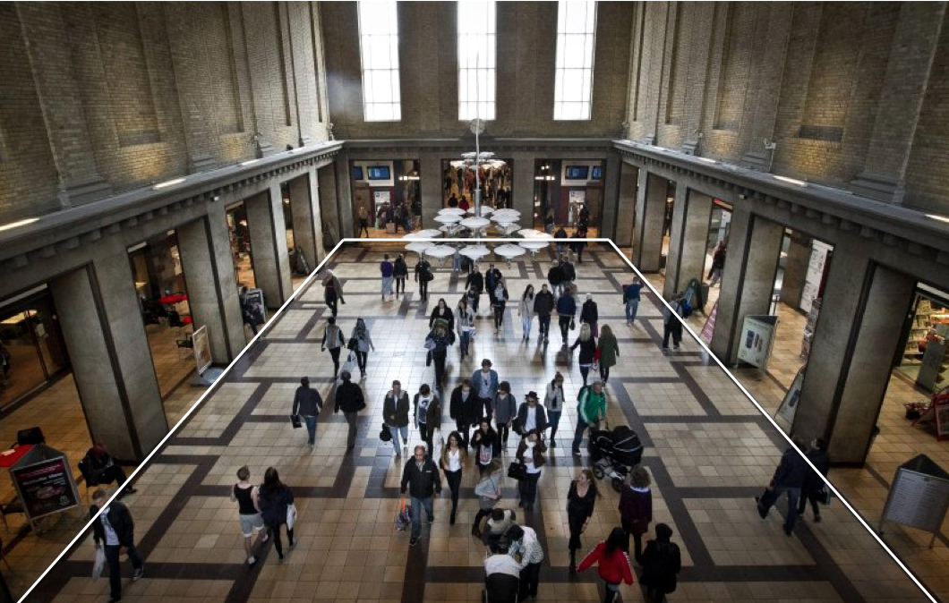
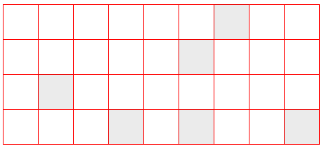
In this lab session we will investigate if it is possible to make a robot stay in the middle of the main hall of Aarhus Banegaard
within the area marked with white lines in Figure 1. This area will be called the
robot arena in the following. Furthermore, we will investigate if it is possible to use the
dark and light brown tiles to localize the robot within the robot arena.
We will use Monte Carlo Localization to localize the robot on a map of the tiles in the robot arena, [2].
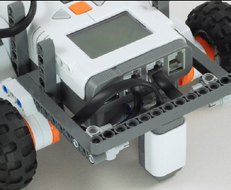
To make the investigation we will use a differential driven car such as the base vehicle of Lesson 6 with a light sensor mounted as shown in Figure 2. The light sensor is going to be used to measure the brightness of the surface underneeth the robot.
In the experiment we will only use the methods travel and rotate of the leJOS class DifferentialPilot to move the robot around and we will use the leJOS class OdometryPoseProvider to make an odometric estimate of the position of the robot within the robot arena while the robot is moving around.
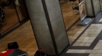
Make the robot stay within the robot arenaFirst of all note that there is an edge around the robot arena, Figure 3. This edge can be detected by sensors on the robot.
Program the robot to stay within the robot arena by making a behavior based control program with two behaviors:
Test the program in a simple model of the robot arena with pillars and dark thin lines to mark the edge. Use the method of the program PilotSquare.java from Lesson 10 to report on the LCD and the PC the estimated position of the robot within the robot arena. Compare this estimate of the robot position with the real position and describe how the error of the estimate develope over time.
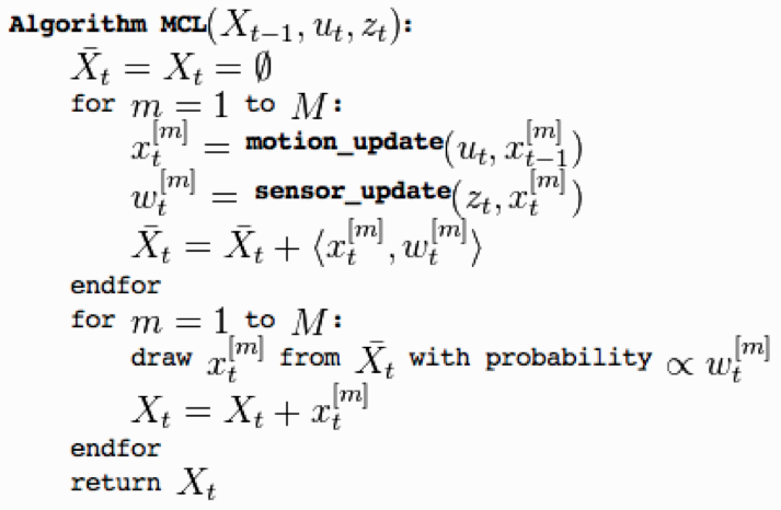
Localization by means of particle filtersNow we will try to estimate the position of the robot within the robot arena more accurately than the accuracy we obtained by means of the odometry estimate. We will use the patterns of dark and light brown tiles in the robot arena and the method of Monte Carlo localization or particle filter localization, [2]: "The algorithm uses a particle filter to represent the distribution of likely states, with each particle representing a possible state, i.e. a hypothesis of where the robot is", Figure 4.
Inspired by the leJOS MCLParticleSet a particle filter localization algorithm has been implemented in the PC program RobotMonitor, [1]. The map used in the program is a 2D model of the tiles in the robot arena, Figure 5.
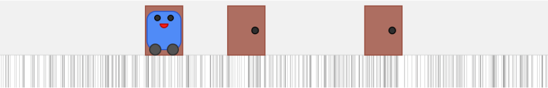
In the RobotMonitor program the method goSimulation show how a sequence of TRAVEL moves and light sensor readings can be simulated to demonstrate how the particles will behave during each step of the Monte Carlo localization algorithm. A simple 1D tile map similar to the patterns of doors in the 1D world in Figure 6 has been used in RobotMonitor. The result after several moves and sensor readings can be seen in Figure 7.
In the RobotMonitor program the motionUpdate method implements the motion_update step of the algorithm, Figure 4. The motion model used in the class Particle is the same as used in the leJOS class MCLParticle with distanceNoiseFactor = 0.02, angleNoiseFactor = 1:
The sensorUpdate method in the RobotMonitor program implements the sensor_update step of the algorithm, Figure 4.
The sensor model used in the class
Particle is:
The initial set of particles have been chosen by the method:
Now we are going to investigate if the localization algorithm implemented in the simulation can be used in
a physical 1D black/white tile world similar to the one in Figure 7. This can be done
in two steps:
Localization while avoiding the edge and objectsHow can you localize the robot moving randomly in a 1D black/white tile world by means of travel and rotate steps while the robot avoids the edges and objects in front of it ? Mount an ultrasonic sensor in front of the robot to detect objects. |